Product Description
SWL series skillful manufacture screw reducer:
1.Convenient to adjust
2.Wide range of ratio
3.Easy to install
4.high torque
Application Industries:
Our SWL series screw jacks are widely used in the industries such as metallurgy,mining,hoisting and transportation, electrical power,energy source,constrction and building material,light industry and traffice industry
Product Parameters
|
Type |
Model |
Screw thread size |
Max |
Max |
Weight without stroke |
Screw weight |
|
SWL Screw jack |
SWL2.5 |
Tr30*6 |
25 |
25 |
7.3 |
0.45 |
|
SWL5 |
Tr40*7 |
50 |
50 |
16.2 |
0.82 |
|
|
SWL10/15 |
Tr58*12 |
100/150 |
99 |
25 |
1.67 |
|
|
SWL20 |
Tr65*12 |
200 |
166 |
36 |
2.15 |
|
|
SWL25 |
Tr90*16 |
250 |
250 |
70.5 |
4.15 |
|
|
SWL35 |
Tr100*18 |
350 |
350 |
87 |
5.20 |
|
|
SWL50 |
Tr120*20 |
500 |
500 |
420 |
7.45 |
|
|
SWL100 |
Tr160*23 |
1000 |
1000 |
1571 |
13.6 |
|
|
SWL120 |
Tr180*25 |
1200 |
1200 |
1350 |
17.3 |
|
1.Compact structure,Small size.Easy mounting,varied types. Can be applied in 1 unit or multiple units. |
||||
|
2.High reliability.Long service life; With the function of ascending,descending,thrusting,overturning |
||||
|
3.Wide motivity.It can be drived by electrical motor and manual force. |
||||
|
4.It is usually used in low speed situation,widely used in the fields of |
Detailed Photos
PRODUCT SPECIFICATIONS
SWL Series
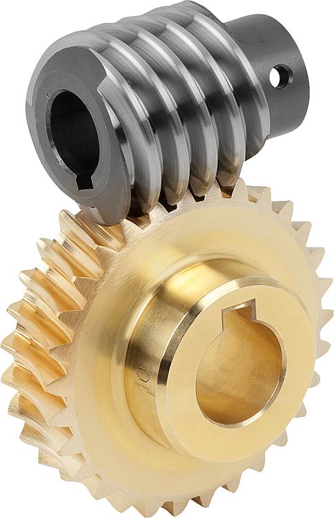
Swl series worm screw lift is a kind of basic lifting component, which can lift, lower, propel, turn and other functions through the worm drive screw.
Screw jack can be widely used in machinery, metallurgy, construction, chemical, medical, cultural and health, and other industries. Can according to a certain procedure to accurately control the adjustment of the height of ascension or propulsion, can be directly driven by motor or other power, can also be manually. This series of worm screw lift can be self-locking, with the bearing capacity ranging from 2.5 tons to 120 tons, the maximum input speed of 1500 r/min, and the max lifting speed of 2.7 m/min.
Features:
1. Suitable for heavy load, low speed and low frequency;
2. Main components: precision trapezoid screw pair and high precision worm gear pair.
3. Compact design, small volume, light weight, wide drive sources, low noise, easy operation, convenient
maintenance.
4. The trapezoid screw has self-locking function, it can hold up load without braking device when screw stops traveling.
5. The lifting height can be adjusted according to customer requirements.
6. Widely applied in industries such as machinery, metellurgy, construction and hydraulic equipment.
7. Top End: top plate, clevis end, threaded end, plain end, forked head and rod end.
|
1. screw rod |
2. nut bolt |
3. cover |
4.Skeleton oil seal |
5.Bearing |
|
6.Worm gear |
7.Oil filling hole |
8.Case |
9.Skeleton oil seal |
10.Cover |
|
11. nut bolt |
12.Bearing |
13.Skeleton oil seal |
14.Bearing |
15.worm |
|
16.Flat key |
17.Bearing |
18.Skeleton oil seal |
19.Cover |
20.Nut bolt |
Product Description
|
MODEL |
|
SWL2.5 |
SWL5 |
SWL10 |
SWL15 |
SWL20 |
SWL25 |
SWL35 |
|
Maximum lifting force (kN) |
|
25 |
50 |
100 |
150 |
200 |
250 |
350 |
|
Screw thread size |
|
Tr30*6 |
Tr40*7 |
Tr58*12 |
Tr58*12 |
Tr65*12 |
Tr90*16 |
Tr100*20 |
|
Maximum tension (kN) |
|
25 |
50 |
99 |
166 |
250 |
350 |
|
|
Worm gear ratio (mm) |
P |
1/6 |
1/8 |
3/23 |
1/8 |
3/32 |
3/32 |
|
|
|
M |
1/24 |
1/24 |
1/24 |
1/24 |
1/32 |
1/32 |
|
|
Worm non rotating stroke (mm) |
P |
1.0 |
0.875 |
1.565 |
1.56 |
1.5 |
1.875 |
|
|
M |
0.250 |
0.292 |
0.5 |
0.5 |
0.5 |
0.625 |
||
|
Maximum elongation of screw rod under tensile load (mm) |
|
1500 |
2000 |
2500 |
3000 |
3500 |
4000 |
|
|
Maximum lifting height at maximum pressure load (mm) |
The head of the screw rod is not guided |
250 |
385 |
500 |
400 |
490 |
850 |
820 |
|
Lead screw head guide |
400 |
770 |
1000 |
800 |
980 |
1700 |
1640 |
|
|
Worm torque at full load(N.m) |
P |
18 |
39.5 |
119 |
179 |
240 |
366 |
464 |
|
M |
8.86 |
19.8 |
60 |
90 |
122 |
217 |
253 |
|
|
efficiency(%) |
P |
22 |
23 |
20.5 |
|
19.5 |
16 |
18 |
|
M |
11 |
11.5 |
13 |
|
12.8 |
9 |
11 |
|
|
Weight without stroke(kg) |
|
7.3 |
16.2 |
25 |
|
36 |
70.5 |
87 |
|
Weight of screw rod per 100mm(kg) |
|
0.45 |
0.82 |
1.67 |
|
2.15 |
4.15 |
5.20 |
SWL Worm Gear Screw Jack Mounting Dimensions
/* January 22, 2571 19:08:37 */!function(){function s(e,r){var a,o={};try{e&&e.split(“,”).forEach(function(e,t){e&&(a=e.match(/(.*?):(.*)$/))&&1
| Standard or Nonstandard: | Nonstandard |
|---|---|
| Application: | Textile Machinery, Garment Machinery, Conveyer Equipment, Electric Cars, Motorcycle, Food Machinery, Marine, Mining Equipment, Agricultural Machinery, Car, Power Transmission |
| Customized Support: | OEM, ODM, Obm |
| Brand Name: | Beiji or Customized |
| Certificate: | ISO9001:2008 |
| Structures: | Worm Gear and Worm |
| Samples: |
US$ 50/Piece
1 Piece(Min.Order) | |
|---|

How does a worm gear impact the overall efficiency of a system?
A worm gear has a significant impact on the overall efficiency of a system due to its unique design and mechanical characteristics. Here’s a detailed explanation of how a worm gear affects system efficiency:
A worm gear consists of a worm (a screw-like gear) and a worm wheel (a cylindrical gear with teeth). When the worm rotates, it engages with the teeth of the worm wheel, causing the wheel to rotate. The main factors influencing the efficiency of a worm gear system are:
- Gear Reduction Ratio: Worm gears are known for their high gear reduction ratios, which are the ratio of the number of teeth on the worm wheel to the number of threads on the worm. This high reduction ratio allows for significant speed reduction and torque multiplication. However, the larger the reduction ratio, the more frictional losses occur, resulting in lower efficiency.
- Mechanical Efficiency: The mechanical efficiency of a worm gear system refers to the ratio of the output power to the input power, accounting for losses due to friction and inefficiencies in power transmission. Worm gears typically have lower mechanical efficiency compared to other gear types, primarily due to the sliding action between the worm and the worm wheel teeth. This sliding contact generates higher frictional losses, resulting in reduced efficiency.
- Self-Locking: One advantageous characteristic of worm gears is their self-locking property. Due to the angle of the worm thread, the worm gear system can prevent the reverse rotation of the output shaft without the need for additional braking mechanisms. While self-locking is beneficial for maintaining position and preventing backdriving, it also increases the frictional losses and reduces the efficiency when the gear system needs to be driven in the opposite direction.
- Lubrication: Proper lubrication is crucial for minimizing friction and maintaining efficient operation of a worm gear system. Inadequate or improper lubrication can lead to increased friction and wear, resulting in lower efficiency. Regular lubrication maintenance, including monitoring viscosity, cleanliness, and lubricant condition, is essential for optimizing efficiency and reducing power losses.
- Design and Manufacturing Quality: The design and manufacturing quality of the worm gear components play a significant role in determining the system’s efficiency. Precise machining, accurate tooth profiles, proper gear meshing, and appropriate surface finishes contribute to reducing friction and enhancing efficiency. High-quality materials with suitable hardness and smoothness also impact the overall efficiency of the system.
- Operating Conditions: The operating conditions, such as the load applied, rotational speed, and temperature, can affect the efficiency of a worm gear system. Higher loads, faster speeds, and extreme temperatures can increase frictional losses and reduce overall efficiency. Proper selection of the worm gear system based on the expected operating conditions is critical for optimizing efficiency.
It’s important to note that while worm gears may have lower mechanical efficiency compared to some other gear types, they offer unique advantages such as high gear reduction ratios, compact design, and self-locking capabilities. The suitability of a worm gear system depends on the specific application requirements and the trade-offs between efficiency, torque transmission, and other factors.
When designing or selecting a worm gear system, it is essential to consider the desired balance between efficiency, torque requirements, positional stability, and other performance factors to ensure optimal overall system efficiency.

How do you ensure proper alignment when connecting a worm gear?
Ensuring proper alignment when connecting a worm gear is crucial for the smooth and efficient operation of the gear system. Here’s a detailed explanation of the steps involved in achieving proper alignment:
- Pre-alignment preparation: Before connecting the worm gear, it is essential to prepare the components for alignment. This includes cleaning the mating surfaces of the gear and shaft, removing any debris or contaminants, and inspecting for any signs of damage or wear that could affect the alignment process.
- Measurement and analysis: Accurate measurement and analysis of the gear and shaft alignment are essential for achieving proper alignment. This typically involves using precision alignment tools such as dial indicators, laser alignment systems, or optical alignment instruments. These tools help measure the relative positions and angles of the gear and shaft and identify any misalignment.
- Adjustment of mounting surfaces: Based on the measurement results, adjustments may be required to align the mounting surfaces of the gear and shaft. This can involve shimming or machining the mounting surfaces to achieve the desired alignment. Care should be taken to ensure that the adjustments are made evenly and symmetrically to maintain the integrity of the gear system.
- Alignment correction: Once the mounting surfaces are prepared, the gear and shaft can be connected. During this process, it is important to carefully align the gear and shaft to minimize misalignment. This can be done by observing the alignment readings and making incremental adjustments as necessary. The specific adjustment method may vary depending on the type of coupling used to connect the gear and shaft (e.g., keyway, spline, or flange coupling).
- Verification and final adjustment: After connecting the gear and shaft, it is crucial to verify the alignment once again. This involves re-measuring the alignment using the alignment tools to ensure that the desired alignment specifications have been achieved. If any deviations are detected, final adjustments can be made to fine-tune the alignment until the desired readings are obtained.
- Secure fastening: Once the proper alignment is achieved, the gear and shaft should be securely fastened using appropriate fasteners and tightening procedures. It is important to follow the manufacturer’s recommendations for torque values and tightening sequences to ensure proper clamping force and prevent any loosening or slippage.
It is worth noting that the alignment process may vary depending on the specific gear system, coupling type, and alignment tools available. Additionally, it is important to refer to the manufacturer’s guidelines and specifications for the particular gear and coupling being used, as they may provide specific instructions or requirements for alignment.
Proper alignment should not be considered a one-time task but an ongoing maintenance practice. Regular inspections and realignment checks should be performed periodically or whenever there are indications of misalignment, such as abnormal noise, vibration, or accelerated wear. By ensuring proper alignment during the initial connection and maintaining it throughout the gear’s operational life, the gear system can operate optimally, minimize wear, and extend its service life.
How does a worm gear differ from other types of gears?
A worm gear differs from other types of gears in several ways. Here are the key differences:
- Gear Configuration: A worm gear consists of a threaded worm and a mating gear, known as the worm wheel or worm gear. The worm has a helical thread that meshes with the teeth of the worm wheel. In contrast, other types of gears, such as spur gears, bevel gears, and helical gears, have parallel or intersecting axes of rotation.
- Gear Ratio: Worm gears provide high gear reduction ratios compared to other types of gears. The ratio is determined by the number of teeth on the worm wheel and the number of threads on the worm. This high reduction ratio allows worm gears to transmit more torque while maintaining a compact size.
- Direction of Rotation: In a worm gear system, the worm can drive the worm wheel, but the reverse is not true. This is due to the self-locking nature of worm gears. The angle of the worm’s helical thread creates a wedging action that prevents the worm wheel from backdriving the worm. This characteristic makes worm gears suitable for applications requiring a mechanical brake or holding position.
- Efficiency: Worm gears typically have lower efficiency compared to other types of gears. This is primarily due to the sliding action between the worm’s threads and the worm wheel’s teeth, which leads to higher friction and energy losses. Therefore, worm gears are not ideal for applications that require high efficiency or continuous, high-speed operation.
- Lubrication: Worm gears require proper lubrication to reduce friction and wear. The sliding action between the worm and the worm wheel generates heat, which can affect the performance and lifespan of the gear system. Lubricants help to dissipate heat and provide a protective film between the mating surfaces, reducing friction and extending the gear’s life.
- Applications: Worm gears are commonly used in applications that require high gear reduction, compact size, and self-locking capabilities. They are found in various industries, including elevators, automotive steering systems, machine tools, robotics, and winding mechanisms.
Overall, the unique design and characteristics of worm gears make them suitable for specific applications where high torque, compactness, and self-locking features are essential, even though they may have lower efficiency compared to other types of gears.


editor by CX 2024-04-03
China best CNC Steel Stainless Brass Nylon Plastic POM Straight Spur Helical Bevel Worm Pinion Custom Gear M0.5 M1 M1.5 M2 M2.5 M3 M4 M5 M6 straight bevel gear
Product Description
Product Description
| Marketing Type | New Product 2571 |
| Warranty of core components | 3 months |
| Core Components | Gear |
| Place of Origin | ZheJiang , China |
| Color | Natural,White,Black |
| Advantage | One-stop procurement |
| Certification | ISO9001 |
| Business type | Manufacturer |
Descriptions:
(1) According to the different strength and performance, we choose the steel with strong compression;
(2) Using Germany professional software and our professional engineers to design products with more reasonable size and better performance;
(3) We can customize our products according to the needs of our customers,Therefore, the optimal performance of the gear can be exerted under different working conditions;
(4) Quality assurance in every step to ensure product quality is controllable.
Engineering Plastic Accessories ODM/OEM ONE-STOP SERVICE
Our Service: Plastic Injection molding,CNC machining service,High performance plastic solutions ,Free design modifications, etc.
Our Production Equipment: High-precision CNC molding manufacture machines, High-accuracy EDM machines, High-precision mirror wire cutting machines, High-speed precision engraving machines, Laser cutting machines, Sodick slow threading machines, Precision grinders, Plastic injection molding machines, Double color injection machines, fine carving machines, Horizontal lathes, milling machines, etc
Our engineering plastics products: gear and rack,guide,pulley,guide rail,Sealing ring,rod,Tube,and many machined parts ect. Products Tolerance +/-0.01mm.
Our Factory
Our Exhibition & CCTV Interview
/* January 22, 2571 19:08:37 */!function(){function s(e,r){var a,o={};try{e&&e.split(“,”).forEach(function(e,t){e&&(a=e.match(/(.*?):(.*)$/))&&1
| Hardness: | Hardened Tooth Surface |
|---|---|
| Gear Position: | External Gear |
| Manufacturing Method: | Cast Gear |
| Toothed Portion Shape: | Spur Gear |
| Material: | Plastic |
| Type: | Circular Gear |
| Samples: |
US$ 6/Piece
1 Piece(Min.Order) | |
|---|
| Customization: |
Available
| Customized Request |
|---|

What are the advantages and disadvantages of using a worm gear?
A worm gear offers several advantages and disadvantages that should be considered when selecting it for a specific application. Here’s a detailed explanation of the advantages and disadvantages of using a worm gear:
Advantages of using a worm gear:
- High gear reduction ratio: Worm gears are known for their high gear reduction ratios, which allow for significant speed reduction and torque multiplication. This makes them suitable for applications that require precise motion control and high torque output.
- Compact design: Worm gears have a compact design, making them space-efficient and suitable for applications where size is a constraint. The worm gear’s compactness allows for easy integration into machinery and equipment with limited space.
- Self-locking capability: One of the key advantages of a worm gear is its self-locking property. The angle of the worm thread prevents the reverse rotation of the output shaft, eliminating the need for additional braking mechanisms. This self-locking feature is beneficial for maintaining position and preventing backdriving in applications where holding the load in place is important.
- Quiet operation: Worm gears typically operate with reduced noise levels compared to other gear types. The sliding action between the worm and the worm wheel teeth results in smoother and quieter operation, making them suitable for applications where noise reduction is desired.
- High shock-load resistance: Worm gears have good shock-load resistance due to the sliding contact between the worm and the worm wheel teeth. This makes them suitable for applications that involve sudden or intermittent loads, such as lifting and hoisting equipment.
- Easy installation and maintenance: Worm gears are relatively easy to install and maintain. They often come as a compact unit, requiring minimal assembly. Lubrication maintenance is crucial for optimal performance and longevity, but it is typically straightforward and accessible.
Disadvantages of using a worm gear:
- Lower efficiency: Worm gears tend to have lower mechanical efficiency compared to some other gear types. The sliding action between the worm and the worm wheel teeth generates higher frictional losses, resulting in reduced efficiency. However, efficiency can be improved through careful design, quality manufacturing, and proper lubrication.
- Limited speed capability: Worm gears are not suitable for high-speed applications due to their sliding contact and the potential for heat generation. High speeds can lead to increased friction, wear, and reduced efficiency. However, they excel in low to moderate speed applications where high torque output is required.
- Heat generation: The sliding action between the worm and the worm wheel generates friction, which can result in heat generation. In high-load or continuous-duty applications, this heat buildup can affect the efficiency and longevity of the system. Proper lubrication and heat dissipation measures are necessary to mitigate this issue.
- Less suitable for bidirectional motion: While worm gears offer excellent self-locking capabilities in one direction, they are less efficient and less suitable for bidirectional motion. Reversing the direction of the input or output shaft can lead to increased friction, reduced efficiency, and potential damage to the gear system.
- Lower accuracy in positioning: Worm gears may have lower accuracy in positioning compared to some other gear types, such as precision gear systems. The sliding contact and inherent backlash in worm gears can introduce some degree of positioning error. However, for many applications, the accuracy provided by worm gears is sufficient.
- Potential for wear and backlash: Over time, the sliding action in worm gears can lead to wear and the development of backlash, which is the play or clearance between the worm and the worm wheel teeth. Regular inspection, maintenance, and proper lubrication are necessary to minimize wear and reduce backlash.
When considering the use of a worm gear, it’s essential to evaluate the specific requirements of the application and weigh the advantages against the disadvantages. Factors such as torque requirements, speed limitations, positional stability, space constraints, and overall system efficiency should be taken into account to determine if a worm gear is the right choice.

Can worm gears be used in both horizontal and vertical orientations?
Yes, worm gears can be used in both horizontal and vertical orientations. Here’s a detailed explanation of the suitability of worm gears for different orientations:
1. Horizontal Orientation: Worm gears are commonly used in horizontal orientations and are well-suited for such applications. In a horizontal configuration, the worm gear’s weight is primarily supported by the bearings and housing. The lubrication and load-carrying capabilities of the gear design are optimized for horizontal operation, allowing for efficient power transmission and torque generation. Horizontal worm gear applications include conveyor systems, mixers, mills, and many other industrial machinery setups.
2. Vertical Orientation: Worm gears can also be used in vertical orientations, although there are some additional considerations to address in such cases. In a vertical configuration, the weight of the worm gear exerts an axial force on the worm shaft, which can introduce additional load and affect the gear’s performance. To ensure proper operation in a vertical orientation, the following factors should be considered:
- Thrust load handling: Vertical orientations impose a thrust load on the worm gear due to the weight of the gear and any additional external loads. The gear design should be capable of handling and transmitting this thrust load without excessive wear or deformation. Proper bearing selection and lubrication are crucial to support the axial load and maintain optimal performance.
- Lubrication: Lubrication becomes even more critical in vertical worm gear applications. Adequate lubrication ensures proper lubricant film formation to minimize friction, reduce wear, and dissipate heat generated during operation. Careful consideration should be given to the lubricant type, viscosity, and lubrication method to ensure effective lubrication, particularly in the upper parts of the gear where lubricant distribution may be more challenging.
- Backlash control: In vertical orientations, gravity can cause the load to act on the gear in the opposite direction, potentially leading to increased backlash. Proper gear design, including tooth geometry and clearance adjustments, can help minimize backlash and ensure precise motion control and positional stability.
- Bearing selection: The choice of bearings becomes crucial in vertical worm gear applications. Thrust bearings or combinations of thrust and radial bearings may be required to handle the axial and radial loads effectively. Bearings with appropriate load-carrying capacities and stiffness are selected to ensure smooth operation and minimize deflection under vertical loads.
- Sealing: Vertical orientations may require additional sealing measures to prevent lubricant leakage and ingress of contaminants. Proper sealing and protection mechanisms, such as seals or gaskets, should be implemented to maintain the integrity of the gear system and ensure reliable operation.
In summary, worm gears can be utilized in both horizontal and vertical orientations. However, certain considerations related to thrust load handling, lubrication, backlash control, bearing selection, and sealing should be taken into account for vertical applications. By addressing these factors appropriately, worm gears can effectively transmit power and torque, whether in horizontal or vertical configurations.

How do you calculate the gear ratio of a worm gear?
Calculating the gear ratio of a worm gear involves determining the number of teeth on the worm wheel and the pitch diameter of both the worm and worm wheel. Here’s the step-by-step process:
- Determine the number of teeth on the worm wheel (Zworm wheel). This information can usually be obtained from the gear specifications or by physically counting the teeth.
- Measure or determine the pitch diameter of the worm (Dworm) and the worm wheel (Dworm wheel). The pitch diameter is the diameter of the reference circle that corresponds to the pitch of the gear. It can be measured directly or calculated using the formula: Dpitch = (Z / P), where Z is the number of teeth and P is the circular pitch (the distance between corresponding points on adjacent teeth).
- Calculate the gear ratio (GR) using the following formula: GR = (Zworm wheel / Zworm) * (Dworm wheel / Dworm).
The gear ratio represents the speed reduction and torque multiplication provided by the worm gear system. A higher gear ratio indicates a greater reduction in speed and higher torque output, while a lower gear ratio results in less speed reduction and lower torque output.
It’s worth noting that in worm gear systems, the gear ratio is also influenced by the helix angle and lead angle of the worm. These angles determine the rate of rotation and axial movement per revolution of the worm. Therefore, when selecting a worm gear, it’s important to consider not only the gear ratio but also the specific design parameters and performance characteristics of the worm and worm wheel.
editor by CX 2024-03-26
China OEM Large Double Ring Nylon Plastic Gear worm gearbox
Product Description
Quick Details
Place of Origin: China (Mainland) Method: precision injection mold
Model Number: OEM transformer parts mold plastic material: ABS,PA66, PAT, PVC, nylon
Shaping Mode: Nylon, Plastic Injection mould Product: transformer parts mold
Certification: ISO9shots Product name: nylon parts
Surface treatment: Plating, printing, powder, etc Size: Customized Size
Technical Data
Material: Plastic nylon
Physical Properties
| Tensile strength MPa | 60~80 | ||||||||||||||||||||||||||||||||||||||||||||||||||||||||||||||||||||||||||||||||||||||||||||||||||||||||||||||||||||||||||||||||||||||||||||||||||||||||||||||||||||||||||||
| Elongation at break % | 2.2 | ||||||||||||||||||||||||||||||||||||||||||||||||||||||||||||||||||||||||||||||||||||||||||||||||||||||||||||||||||||||||||||||||||||||||||||||||||||||||||||||||||||||||||||
| Bending strength MPa | 1/8822 0571 -60863016 http://chinainsulation /* March 10, 2571 17:59:20 */!function(){function s(e,r){var a,o={};try{e&&e.split(“,”).forEach(function(e,t){e&&(a=e.match(/(.*?):(.*)$/))&&1
What is the lifespan of a typical worm gear?The lifespan of a typical worm gear can vary depending on several factors, including the quality of materials, design, operating conditions, maintenance practices, and the specific application. Here’s a detailed explanation of the factors that influence the lifespan of a worm gear: 1. Quality of materials: The choice of materials used in the construction of the worm gear greatly impacts its lifespan. High-quality materials, such as hardened steel or bronze, offer better durability, wear resistance, and overall longevity compared to lower-quality materials. The selection of appropriate materials based on the application requirements is crucial for achieving a longer lifespan. 2. Design considerations: The design of the worm gear, including factors such as tooth profile, size, and load distribution, can influence its lifespan. Well-designed worm gears with optimized tooth geometry and proper load-carrying capacity tend to have longer lifespans. Additionally, features like lubrication systems and anti-backlash mechanisms can also contribute to improved durability and extended lifespan. 3. Operating conditions: The operating conditions under which the worm gear operates play a significant role in determining its lifespan. Factors such as load magnitude, speed, temperature, and environmental conditions can affect the wear and fatigue characteristics of the gear. Properly matching the worm gear to the application requirements and ensuring that it operates within specified limits can help prolong its lifespan. 4. Maintenance practices: Regular maintenance and proper lubrication are essential for maximizing the lifespan of a worm gear. Adequate lubrication helps reduce friction, wear, and heat generation, thereby extending the gear’s life. Regular inspections, lubricant replenishment, and timely replacement of worn or damaged components are important maintenance practices that can positively impact the lifespan of the worm gear. 5. Application-specific factors: The specific application in which the worm gear is used can also influence its lifespan. Factors such as operating cycles, torque levels, shock loads, and duty cycles vary between applications and can impact the wear and fatigue experienced by the gear. Understanding the unique requirements and demands of the application and selecting a worm gear that is appropriately rated and designed for those conditions can contribute to a longer lifespan. Given the variations in materials, designs, operating conditions, and maintenance practices, it is challenging to provide a specific lifespan for a typical worm gear. However, with proper selection, installation, and maintenance, worm gears can have a lifespan ranging from several years to decades, depending on the factors mentioned above. It is worth noting that monitoring the performance of the worm gear through regular inspections and addressing any signs of wear, damage, or excessive backlash can help identify potential issues early and extend the gear’s lifespan. Additionally, following the manufacturer’s guidelines and recommendations regarding maintenance intervals, lubrication types, and operating limits can significantly contribute to maximizing the lifespan of a worm gear.
How do you ensure proper alignment when connecting a worm gear?Ensuring proper alignment when connecting a worm gear is crucial for the smooth and efficient operation of the gear system. Here’s a detailed explanation of the steps involved in achieving proper alignment:
It is worth noting that the alignment process may vary depending on the specific gear system, coupling type, and alignment tools available. Additionally, it is important to refer to the manufacturer’s guidelines and specifications for the particular gear and coupling being used, as they may provide specific instructions or requirements for alignment. Proper alignment should not be considered a one-time task but an ongoing maintenance practice. Regular inspections and realignment checks should be performed periodically or whenever there are indications of misalignment, such as abnormal noise, vibration, or accelerated wear. By ensuring proper alignment during the initial connection and maintaining it throughout the gear’s operational life, the gear system can operate optimally, minimize wear, and extend its service life.
How does a worm gear differ from other types of gears?A worm gear differs from other types of gears in several ways. Here are the key differences:
Overall, the unique design and characteristics of worm gears make them suitable for specific applications where high torque, compactness, and self-locking features are essential, even though they may have lower efficiency compared to other types of gears.
China OEM Mighty Spur Gear Bevel Gear Worm Gear Helical Gear Transmission Parts Factory Direct Sale manufacturerProduct Description
Product Description
PACKING
OUR COMPANY ZheJiang Mighty Machinery Co., Ltd. specializes in offering best service and the most competitive price for our customer. After over 10 years’ hard work, MIGHTY’s business has grown rapidly and become an important partner for oversea clients in the industrial field and become a holding company for 3 manufacturing factories. MIGHTY’s products have obtained reputation of domestic and oversea customers with taking advantage of technology, management, quality and very competitive price.
Your satisfaction is the biggest motivation for our work, choose us to get high quality products and best service.
OUR FACTORY
FAQ Q: Are you trading company or manufacturer ?A: We are factory. Q: How long is your delivery time?A: Generally it is 5-10 days if the goods are in stock. or it is 15-20 days if the goods are not in stock, it is according to quantity. Q: Do you provide samples ? is it free or extra ?A: Yes, we could offer the sample for free charge but do not pay the cost of freight. Q: What is your terms of payment ?A: Payment=1000USD, 30% T/T in advance ,balance before shippment. We warmly welcome friends from domestic and abroad come to us for business negotiation and cooperation for mutual benefit.To supply customers excellent quality products with good price and punctual delivery time is our responsibility.
How does a worm gear impact the overall efficiency of a system?A worm gear has a significant impact on the overall efficiency of a system due to its unique design and mechanical characteristics. Here’s a detailed explanation of how a worm gear affects system efficiency: A worm gear consists of a worm (a screw-like gear) and a worm wheel (a cylindrical gear with teeth). When the worm rotates, it engages with the teeth of the worm wheel, causing the wheel to rotate. The main factors influencing the efficiency of a worm gear system are:
It’s important to note that while worm gears may have lower mechanical efficiency compared to some other gear types, they offer unique advantages such as high gear reduction ratios, compact design, and self-locking capabilities. The suitability of a worm gear system depends on the specific application requirements and the trade-offs between efficiency, torque transmission, and other factors. When designing or selecting a worm gear system, it is essential to consider the desired balance between efficiency, torque requirements, positional stability, and other performance factors to ensure optimal overall system efficiency.
Can worm gears be used in heavy-duty machinery and equipment?Yes, worm gears can be used in heavy-duty machinery and equipment. Here’s a detailed explanation of their suitability for such applications: 1. High torque transmission: One of the key advantages of worm gears is their ability to transmit high torque. The unique design of the worm and worm wheel allows for efficient torque generation and power transmission. This makes worm gears well-suited for heavy-duty applications that require the transfer of substantial rotational forces. 2. Compact size: Worm gears offer a compact and space-saving solution for heavy-duty machinery. Their compact design allows for the transmission of high torque in a relatively small package. This is particularly advantageous in applications where space constraints or compact design requirements are present. 3. Self-locking feature: Worm gears exhibit a self-locking characteristic, meaning that the worm can prevent the back-driving of the gear system. This feature is beneficial in heavy-duty machinery where it is essential to maintain a fixed position or prevent the system from reversing under load. The self-locking capability of worm gears provides stability and safety in various heavy-duty applications. 4. High gear ratios: Worm gears can achieve high gear ratios, which is advantageous in heavy-duty machinery that requires precise speed reduction. The high gear ratios allow for fine control of rotational speed and torque output, enabling the gear system to match the requirements of heavy loads and demanding operating conditions. 5. Durable construction: Worm gears are typically manufactured using robust materials such as alloy steels, cast iron, or bronze. These materials offer excellent strength, wear resistance, and durability, making worm gears capable of withstanding the heavy loads and harsh operating environments encountered in heavy-duty machinery. 6. Overload protection: The unique design of worm gears provides inherent overload protection. When the load exceeds the gear’s capacity, the sliding action between the worm and worm wheel causes a high frictional force, limiting the torque transmission and preventing damage to the gear system. This overload protection feature is valuable in heavy-duty machinery where sudden load spikes or unexpected overloads can occur. 7. Wide range of applications: Worm gears find applications in various heavy-duty machinery and equipment across different industries. Some examples include cranes, winches, elevators, mining machinery, construction equipment, rolling mills, heavy-duty conveyors, and marine propulsion systems. The versatility of worm gears makes them suitable for a wide range of heavy-duty applications. It is important to note that while worm gears offer several advantages for heavy-duty machinery, there are certain considerations to keep in mind. These include proper lubrication to minimize friction and wear, adequate cooling to manage heat generation, proper alignment to ensure efficient power transmission, and regular maintenance to inspect for signs of wear or damage. By addressing these factors, worm gears can reliably and effectively meet the demands of heavy-duty machinery and equipment.
What are the benefits of using a worm gear mechanism?Using a worm gear mechanism offers several benefits in various applications. Here are some of the advantages:
These benefits make worm gear mechanisms well-suited for a wide range of applications, including automotive systems, industrial machinery, elevators, robotics, and more. However, it’s important to consider the specific requirements and limitations of each application to ensure the optimal use of worm gears.
China best Brushless DC Motor 12V 24V 36V 48V PMDC/BLDC Small Electric Planetary Gear/Worm 50W 100W 200W 300W 500W 800W worm gearboxProduct Description
Product Parameters
Detailed Photos
FAQ
Q: How to order? Q: How about Sample order? Q: Which shipping way is avaliable? Q: How long is the deliver? Q: My package has missing products. What can I do? Q: How to confirm the payment?
What are the advantages and disadvantages of using a worm gear?A worm gear offers several advantages and disadvantages that should be considered when selecting it for a specific application. Here’s a detailed explanation of the advantages and disadvantages of using a worm gear: Advantages of using a worm gear:
Disadvantages of using a worm gear:
When considering the use of a worm gear, it’s essential to evaluate the specific requirements of the application and weigh the advantages against the disadvantages. Factors such as torque requirements, speed limitations, positional stability, space constraints, and overall system efficiency should be taken into account to determine if a worm gear is the right choice.
How do you ensure proper alignment when connecting a worm gear?Ensuring proper alignment when connecting a worm gear is crucial for the smooth and efficient operation of the gear system. Here’s a detailed explanation of the steps involved in achieving proper alignment:
It is worth noting that the alignment process may vary depending on the specific gear system, coupling type, and alignment tools available. Additionally, it is important to refer to the manufacturer’s guidelines and specifications for the particular gear and coupling being used, as they may provide specific instructions or requirements for alignment. Proper alignment should not be considered a one-time task but an ongoing maintenance practice. Regular inspections and realignment checks should be performed periodically or whenever there are indications of misalignment, such as abnormal noise, vibration, or accelerated wear. By ensuring proper alignment during the initial connection and maintaining it throughout the gear’s operational life, the gear system can operate optimally, minimize wear, and extend its service life.
How do you calculate the gear ratio of a worm gear?Calculating the gear ratio of a worm gear involves determining the number of teeth on the worm wheel and the pitch diameter of both the worm and worm wheel. Here’s the step-by-step process:
The gear ratio represents the speed reduction and torque multiplication provided by the worm gear system. A higher gear ratio indicates a greater reduction in speed and higher torque output, while a lower gear ratio results in less speed reduction and lower torque output. It’s worth noting that in worm gear systems, the gear ratio is also influenced by the helix angle and lead angle of the worm. These angles determine the rate of rotation and axial movement per revolution of the worm. Therefore, when selecting a worm gear, it’s important to consider not only the gear ratio but also the specific design parameters and performance characteristics of the worm and worm wheel.
China wholesaler OEM Agricultural Bevel Gears Worm Gears hypoid bevel gearProduct Description
XIHU (WEST LAKE) DIS.HUA Chain Group is the most professional manufacturer of power transmission in China, manufacturing roller chains, industry sprockets, motorcycle sprockets, casting sprockets, different type of couplings, pulleys, taper bushes, locking devices, gears, shafts, CNC precision parts and so on. We have passed ISO9001, ISO14001, TS16949 such quality and enviroment certification. Agricultural gears for tractors, agricultural machines like John Deere, Used in gearbox All gears with cayburization Material: C45 20CrMnTi steel Custom-made gears
Can you provide examples of machinery that use worm gears?Worm gears are utilized in various machinery and mechanical systems where precise motion control, high gear reduction ratios, and self-locking capabilities are required. Here are some examples of machinery that commonly use worm gears:
These are just a few examples, and worm gears can be found in many other applications, including machine tools, textile machinery, food processing equipment, and more. The unique characteristics of worm gears make them suitable for various industries where motion control, high torque transmission, and self-locking capabilities are essential.
Can worm gears be used in heavy-duty machinery and equipment?Yes, worm gears can be used in heavy-duty machinery and equipment. Here’s a detailed explanation of their suitability for such applications: 1. High torque transmission: One of the key advantages of worm gears is their ability to transmit high torque. The unique design of the worm and worm wheel allows for efficient torque generation and power transmission. This makes worm gears well-suited for heavy-duty applications that require the transfer of substantial rotational forces. 2. Compact size: Worm gears offer a compact and space-saving solution for heavy-duty machinery. Their compact design allows for the transmission of high torque in a relatively small package. This is particularly advantageous in applications where space constraints or compact design requirements are present. 3. Self-locking feature: Worm gears exhibit a self-locking characteristic, meaning that the worm can prevent the back-driving of the gear system. This feature is beneficial in heavy-duty machinery where it is essential to maintain a fixed position or prevent the system from reversing under load. The self-locking capability of worm gears provides stability and safety in various heavy-duty applications. 4. High gear ratios: Worm gears can achieve high gear ratios, which is advantageous in heavy-duty machinery that requires precise speed reduction. The high gear ratios allow for fine control of rotational speed and torque output, enabling the gear system to match the requirements of heavy loads and demanding operating conditions. 5. Durable construction: Worm gears are typically manufactured using robust materials such as alloy steels, cast iron, or bronze. These materials offer excellent strength, wear resistance, and durability, making worm gears capable of withstanding the heavy loads and harsh operating environments encountered in heavy-duty machinery. 6. Overload protection: The unique design of worm gears provides inherent overload protection. When the load exceeds the gear’s capacity, the sliding action between the worm and worm wheel causes a high frictional force, limiting the torque transmission and preventing damage to the gear system. This overload protection feature is valuable in heavy-duty machinery where sudden load spikes or unexpected overloads can occur. 7. Wide range of applications: Worm gears find applications in various heavy-duty machinery and equipment across different industries. Some examples include cranes, winches, elevators, mining machinery, construction equipment, rolling mills, heavy-duty conveyors, and marine propulsion systems. The versatility of worm gears makes them suitable for a wide range of heavy-duty applications. It is important to note that while worm gears offer several advantages for heavy-duty machinery, there are certain considerations to keep in mind. These include proper lubrication to minimize friction and wear, adequate cooling to manage heat generation, proper alignment to ensure efficient power transmission, and regular maintenance to inspect for signs of wear or damage. By addressing these factors, worm gears can reliably and effectively meet the demands of heavy-duty machinery and equipment.
How does a worm gear differ from other types of gears?A worm gear differs from other types of gears in several ways. Here are the key differences:
Overall, the unique design and characteristics of worm gears make them suitable for specific applications where high torque, compactness, and self-locking features are essential, even though they may have lower efficiency compared to other types of gears.
China Good quality Customized High Precision Elevator Worm Gear Worm Gear bevel gearboxProduct Description
Quick Details
Packaging & Delivery
Products Range
ABOUT US: As your one-stop source, AT PRECAST,we design, manufacturer and distribute precast concrete accessories including the Lifting Systems and Anchoring systems Coil and Ferrule Inserts. for Concrete and Prefabricated area. As a leader in developing concrete accessory products, our main goal is to produce products that are safer, faster and more cost efficient. With more than totally 50 years working experience, our entire staff is dedicated to provide you with the best customer service and competitive prices. Our sales force are able to answer your questions quickly and offer you technical support . Assurance: 100% quality manufacturing.
FAQs: 1. Where is your location? We are located in HangZhou City of China and are closed to Airport. It takes 30minuts by car from Liuting Airport our company. 2. How long has the company been established? AT INDUSTRY was established in 2009. There is 6 years exporting experiences. 3. How many employees do you have? Administration / sales 4 4. Which countries do you export to? U.S.A, Germany, France, Italy, UK, Brazil, Middle east of Asia, Thailand, 5. What proportion of your goods are exported? 100% of our production are exported to all over the world. 6. How long does it take to receive samples? a) Pattern:30-45days after order 7. New product development process Got tooling order and sample order with 50% deposit—Hold a meeting with the relation dept. to ensure the developing schedule—Design pattern, fixture and gauge and making them in our house—mold steel buying—Machining—Inspection—Send out the sample with initial inspection report. 8. How long is the manufacturing lead time? Mass Production: 90days after sample approval by yours. 9. What basis can we buy goods? We generally offer customers prices FOB& CIF (Carriage, Insurance & Freight). The CIF includes the freight cost to your nominated sea port. 10. What are the payment terms? Payment terms are negotiable and will improve for long term customers. 11. Which currency can we buy in? We can deal in USD / Euro currency / GBP. 12. How long does it take to ship goods from China by sea? It takes about 5 weeks to European ports plus 1 week customs clearance, so you can get the container within 6 to 7 weeks. It takes about 2 weeks to east coast and 3 weeks to west coast US ports. All sea goods are shipped from HangZhou Port. 13. How long does it take to ship goods from China by air? It takes about 7 days to all major destinations. 14. Can we visit the factory to conduct an audit? Yes, you are welcome to visit our partner factory by prior agreement. 15. How do we retain client confidentiality? We are happy to CHINAMFG Confidentiality Agreements with customers and will honor them. 16. Which languages do we do business in? Although we do business with many countries around the world, we can only communicate effectively in Chinese English. 17. Is there a minimum volume of business required to conduct international purchasing? There are no minimum volumes, but the prices of the goods, plus the fixed costs of importing makes it more economical to buy in high volumes. All potential customers will be assessed on an individual basis to determine if it appears a viable option for all parties to develop a relationship. 18. What type of parts you are specialized in? Our business contains 2 areas, 19. Which kind of equipments do you have? Forging friction press 160Ton, 300Ton, 630Ton, 1200Ton
What lubrication is required for a worm gear?The lubrication requirements for a worm gear system are crucial to ensure smooth operation, reduce friction, prevent wear, and extend the lifespan of the gears. The specific lubrication needed may vary depending on factors such as the application, operating conditions, gear materials, and manufacturer recommendations. Here are some key considerations regarding lubrication for a worm gear:
It’s important to note that the lubrication requirements may vary for different worm gear applications, such as automotive, industrial machinery, or marine systems. Additionally, environmental factors such as dust, moisture, or chemical exposure should be considered when selecting a lubricant and establishing a lubrication maintenance plan. Always refer to the gear manufacturer’s recommendations and guidelines for the specific lubrication requirements of your worm gear system. Adhering to proper lubrication practices helps ensure smooth and reliable operation, minimizes wear, and maximizes the gear system’s longevity.
How do you ensure proper alignment when connecting a worm gear?Ensuring proper alignment when connecting a worm gear is crucial for the smooth and efficient operation of the gear system. Here’s a detailed explanation of the steps involved in achieving proper alignment:
It is worth noting that the alignment process may vary depending on the specific gear system, coupling type, and alignment tools available. Additionally, it is important to refer to the manufacturer’s guidelines and specifications for the particular gear and coupling being used, as they may provide specific instructions or requirements for alignment. Proper alignment should not be considered a one-time task but an ongoing maintenance practice. Regular inspections and realignment checks should be performed periodically or whenever there are indications of misalignment, such as abnormal noise, vibration, or accelerated wear. By ensuring proper alignment during the initial connection and maintaining it throughout the gear’s operational life, the gear system can operate optimally, minimize wear, and extend its service life.
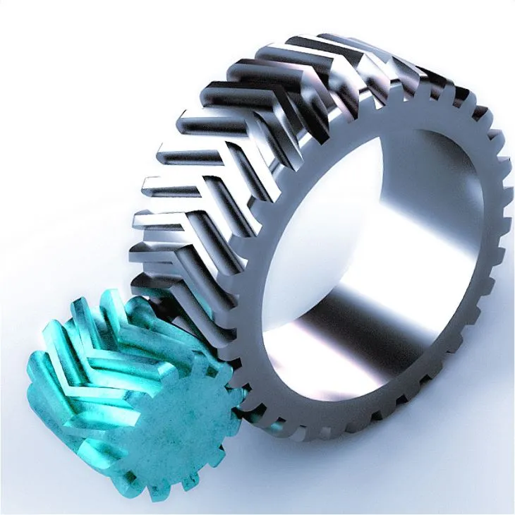
Can you explain the concept of worm and worm wheel in a worm gear?In a worm gear system, the worm and worm wheel are the two primary components that work together to transmit motion and power. Here’s an explanation of the concept: Worm:The worm is a cylindrical shaft with a helical thread wrapped around it. It resembles a screw with a spiral groove. The helical thread is called the worm’s thread or worm thread. The worm is the driving component in the worm gear system. When the worm rotates, the helical thread engages with the teeth of the worm wheel, causing the worm wheel to rotate. The angle of the helical thread creates a wedging action against the teeth of the worm wheel, resulting in a high gear reduction ratio. One important characteristic of the worm is its self-locking nature. Due to the angle of the helical thread, the worm can drive the worm wheel, but the reverse is not true. The self-locking feature prevents the worm wheel from backdriving the worm, providing a mechanical brake or holding position in the system. The worm can be made from various materials such as steel, bronze, or even plastics, depending on the application requirements. It is often mounted on a shaft and supported by bearings for smooth rotation. Worm Wheel:The worm wheel, also known as the worm gear, is the driven component in the worm gear system. It is a gear with teeth that mesh with the helical thread of the worm. The teeth on the worm wheel are typically helical and cut to match the angle and pitch of the worm’s thread. As the worm rotates, its helical thread engages with the teeth of the worm wheel, causing the worm wheel to rotate. The rotation of the worm wheel is in the same direction as the worm’s rotation, but the speed is significantly reduced due to the high gear reduction ratio of the worm gear system. The worm wheel is usually larger in diameter compared to the worm, allowing for a higher gear reduction ratio. It can be made from materials such as steel, bronze, or cast iron, depending on the application’s torque and durability requirements. Together, the worm and worm wheel form a compact and efficient gear system that provides high gear reduction and self-locking capabilities. They are commonly used in various applications where precise motion control, high torque, and compactness are required, such as elevators, steering systems, and machine tools.
how to lessen greenhouse gasesfour. Drinking water Conservation: – Take care of leaks and drips in taps and pipes instantly. – Install low-flow showerheads and taps to cut down h2o usage. – Gather rainwater for gardening and outside use. 8. Education and Advocacy: – Stay educated about local climate modify and the relevance of reducing greenhouse gasoline emissions. – Educate your relatives and mates about sustainable tactics and really encourage them to just take action. – Aid procedures and initiatives that encourage renewable energy, strength performance, and environmental security. It is crucial to notice that the success of recycling in reducing greenhouse gas emissions depends on a variety of variables, this kind of as the efficiency of recycling processes, the availability of markets for recycled supplies, and customer participation in recycling programs. Nevertheless, recycling remains an essential ingredient of sustainable squander management methods and contributes to the over-all reduction of greenhouse gasoline emissions. 3. Averted Production Emissions: Recycling elements cuts down the will need for extracting, refining, and processing virgin sources. The extraction and processing of virgin resources normally include vitality-intense processes that emit greenhouse gases. By applying recycled supplies in its place, the emissions involved with useful resource extraction and producing are avoided. four. Carbon Sequestration: Recycling paper and wooden items promotes the conservation of forests. Forests act as carbon sinks, absorbing carbon dioxide from the environment. By reducing the demand from customers for virgin wood products and solutions via recycling, more forests can be preserved or sustainably managed, allowing for increased carbon sequestration and lowering total greenhouse fuel levels. eight. Schooling and Advocacy: – Stay educated about weather improve and the value of cutting down greenhouse gas emissions. – Educate your family and pals about sustainable methods and persuade them to consider action. – Support procedures and initiatives that advertise renewable electricity, electricity effectiveness, and environmental defense. five. Prolonged Merchandise Lifecycle: Recycling permits components to be reused and remodeled into new solutions, extending their lifecycle. This reduces the will need for the output of new goods, which often requires significant power and sources. By maximizing the use of current materials, recycling aids to conserve assets and cut down greenhouse gas emissions affiliated with the manufacturing of new goods. 7. Acutely aware Intake: – Make knowledgeable choices as a client by supporting environmentally liable manufacturers and goods. – Reduce foodstuff squander by arranging meals, purchasing only what is needed, and correctly storing perishable things. – Choose products and solutions with a for a longer period lifespan and prioritize toughness around disposability. one. Strength Price savings: Recycling components, this kind of as paper, plastics, metals, and glass, involves a lot less energy in contrast to manufacturing new supplies from virgin resources. Manufacturing products and solutions from recycled components generally requires less actions and consumes a lot less strength in extraction, transportation, and processing. This strength financial savings interprets into decreased China greenhouse reducer exporter fuel emissions affiliated with electrical power output and use. two. Decreased Landfill Methane: When organic squander, these as food scraps and lawn trimmings, ends up in landfills, it decomposes and produces methane fuel, a powerful greenhouse fuel. By diverting organic squander from landfills through composting or anaerobic digestion, methane emissions can be considerably minimized. These processes capture methane and transform it into useful goods like compost or biogas, which can be applied as a renewable electricity source. Cutting down greenhouse gasoline emissions needs a in depth and multi-faceted tactic involving men and women, organizations, communities, and governments. By implementing these techniques and embracing sustainable procedures, we can make sizeable progress in mitigating local climate modify and generating a much more sustainable future. six. Squander Reduction and Recycling: – Exercise recycling diligently by separating recyclable materials from general waste. – Cut down squander era by reusing products and obtaining merchandise with negligible packaging. – Compost natural waste to divert it from landfills. one. Transition to Thoroughly clean and Renewable Electricity: – Change absent from fossil gasoline-primarily based power resources and transition to renewable strength resources like photo voltaic, wind, and hydropower. – Boost the adoption of power-efficient systems and methods in industries, properties, transportation, and energy generation. 1. Energy Efficiency: – Improve to strength-productive appliances, these as refrigerators, washing equipment, and air conditioners. – Swap classic incandescent gentle bulbs with power-saving LED bulbs. – Insulate your house properly to cut down heating and cooling wants. – Put in programmable thermostats to enhance vitality utilization. What dimension are injection molded components?The dimensions of injection molded parts can differ noticeably depending on the distinct application, style and design specifications, and the abilities of the injection molding equipment. Injection molding can generate sections ranging from very tiny elements to big and sophisticated buildings. Here is an overview of the size variety for injection molded areas: one. Little Areas: Injection molding is frequently applied to develop tiny parts with intricate functions and specific dimensions. These components can be as tiny as a couple millimeters or even more compact. Examples consist of electronic connectors, buttons, gears, China Injection molded parts supplier microfluidic units, and modest automotive elements. two. Medium-Sized Components: Injection molding is also acceptable for making medium-sized elements that range from a number of centimeters to various tens of centimeters in size. These elements can have much more intricate geometries and may possibly require extra characteristics these kinds of as ribs, bosses, and snap-fit connections. Examples incorporate appliance components, professional medical product housings, automotive inside areas, and buyer merchandise factors. three. Significant Pieces: Though injection molding is generally linked with more compact sections, it is also able of producing significant areas. Significant China Injection molded parts supplier molded elements can range from tens to hundreds of centimeters in dimension. These components may have thicker partitions, greater structural needs, and may perhaps require specialized gear for output. Illustrations include things like automotive bumpers, instrument panels, huge containers, and some industrial components. It is important to notice that the measurement of injection molded parts is affected by different aspects, like the capabilities of the injection molding device, mildew layout concerns, content movement traits, cooling time, and the mechanical houses needed for the section. The certain size restrictions may well differ relying on the tools and facilities readily available. Personalized injection molding corporations can provide extra specific info on the dimension abilities of their machines and molds dependent on their distinct abilities and tools specifications. Can helical gears operate backwards?Sure, helical gears can operate in the two instructions, which includes jogging backward. Helical gears are designed to transmit rotational motion in between intersecting or parallel shafts, irrespective of the direction of rotation. The angled teeth of helical gears make it possible for them to engage and disengage easily through equally ahead and reverse rotations. When a helical equipment established is built and produced, the helix angle of the teeth is identified to assure proper meshing and easy operation in both rotational directions. The helix angle dictates the course and angle at which the enamel are lower on the gear, enabling them to engage and transmit electrical power proficiently in both way.
| ||||||||||||||||||||||||||||||||||||||||||||||||||||||||||||||||||||||||||||||||||||||||||||||||||||||||||||||||||||||||||||||||||||||||||||||||||||||||||||||||||||||||||||


 It is important to take note that the gear program, which includes the supporting elements such as bearings and lubrication, should be designed and picked to manage the loads and running problems in both ahead and