Product Description
CHINAMFG Bearing is short for HangZhou CHINAMFG SPECIAL HEAVY-DUTY AND LARGE BEARING MANUFACTURING CO.;,; LTD.;
.; Introduction of CHINAMFG heavy load slewing drive
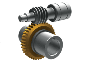
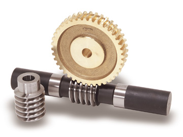
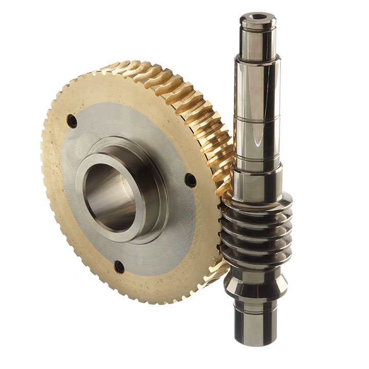
Slewing Drive is also called slewing gear,; worm gear,; worm drive,; rotary drive,; slew drive,; worm gear reducer and rotary drive unit.; At present the majority of such devices are caller Slewing Drive.;
LYHY heavy load slewing drive is usually composed of a slewing ring,; worm,; casting housing,; and standard components likebearing and bolts,; etc.; While used in photovoltaic power generation system,; the slewing drive is usually used in combination with DC planetary speed reducer motor and AC speed reducer motor.; While used in engineering equipment,; it is regularly used in combination with hydraulic motor to function as power driving system.;
2.; Structure
According to the raceway diameter of the slewing ring,; a heavy load slewing drive include M3 ich,; M5 inch,; M7 inch,; M9 inch,; M12 inch,; M14 inch,; M17 inch,; M21 inch,; M25inch,; H14 inch,; H17 inch,; H21 inch and H25 inch.;
3.; Features:;
Heavy load slewing drive is a special bearing.; And a slewing drive is usually composed of a slewing ring,; worm,; casting housing,; and standard components like bearing and bolts,; etc.;
Slewing drive is able to sustain more axial load,; radial load and tilting moment.; Turntable or frame rotates at azimuth and elevation driven by slewing drive.;
4.; Application:;
Slewing drives are widely used in solar power generation tracking system,; timber grab,; special vehicle,; heavy-duty flat-panel truck,; container cranes,; overhead working truck,; truck mounted crane,; automobile crane and aerial vehicles,; cranes,; gantry cranes,; small wind power stations,; space communications,; satellite receiver,; etc.;
LYHY can also design and make other standard and non-standard Slewing Drives as per customer’s different technical requirements.; For more information about the slewing drive,; please contact CHINAMFG Bearing sales department.; We will give you the best technical support.;
| Model | Rated output torque /KN-m | Tilting Moment torque /KN-m | Load /KN | Gear ratio | Self-locking gears | Weight (KG); | |||
| Static load rating,; axial | Static load rating,;radial | Dynamic load rating,; axial | Dynamic load rating,;radial | ||||||
| 3″ | 0.;25 | 0.;5 | 30 | 16.;6 | 9.;6 | 8.;4 | 62:;01:;00 | yes | 12 |
| 5″ | 0.;37 | 0.;8 | 76 | 22.;6 | 13.;8 | 11.;8 | 62:;01:;00 | yes | 18 |
| 7″ | 1.;3 | 13.;5 | 133 | 53 | 32 | 28 | 73:;01:;00 | yes | 23 |
| 9″ | 9.;2 | 33.;9 | 338 | 135 | 81 | 71 | 61:;01:;00 | yes | 50 |
| 12″ | 11.;7 | 54.;3 | 475 | 190 | 114 | 100 | 78:;01:;00 | yes | 60 |
| 14″ | 12.;7 | 67.;8 | 555 | 222 | 133 | 117 | 85:;01:;00 | yes | 73 |
| 17″ | 18.;5 | 135.;6 | 975 | 390 | 235 | 205 | 102:;01:;00 | yes | 110 |
| 21″ | 29 | 203 | 1598 | 640 | 385 | 335 | 125:;01:;00 | yes | 158 |
| 25″ | 34 | 271 | 2360 | 945 | 590 | 470 | 150:;01:;00 | yes | 230 |
| Application: | Agricultural |
|---|---|
| Hardness: | Hardened |
| Manufacturing Method: | Rolling Gear |
| Toothed Portion Shape: | Curved Gear |
| Material: | Bearing Steel |
| Type: | Worm And Wormwheel |
| Customization: |
Available
| Customized Request |
|---|

How do you maintain and service a worm gear?
Maintaining and servicing a worm gear is essential to ensure its optimal performance, reliability, and longevity. Regular maintenance helps identify and address potential issues before they escalate, minimizes wear, and extends the lifespan of the gear system. Here are some key steps involved in maintaining and servicing a worm gear:
- Inspection: Conduct routine visual inspections of the worm gear system to check for any signs of wear, damage, or misalignment. Inspect the gear teeth, bearings, housings, and lubrication system. Look for indications of excessive wear, pitting, chipping, or abnormal noise during operation.
- Lubrication: Ensure that the worm gear system is properly lubricated according to the manufacturer’s recommendations. Regularly check the lubricant levels, cleanliness, and viscosity. Monitor and maintain the lubrication system, including oil reservoirs, filters, and seals. Replace the lubricant at recommended intervals or if it becomes contaminated or degraded.
- Tighten fasteners: Over time, vibrations and operational forces can cause fasteners to loosen. Regularly check and tighten any bolts, screws, or clamps associated with the worm gear system. Be cautious not to overtighten, as it may lead to distortion or damage to the gear components.
- Alignment: Check the alignment of the worm gear system periodically. Misalignment can cause excessive wear, increased friction, and reduced efficiency. Adjust and realign the gears if necessary to ensure proper meshing and minimize backlash.
- Cleaning: Keep the worm gear system clean and free from debris, dirt, or contaminants. Regularly remove any accumulated dirt or particles that may affect the gear performance. Use appropriate cleaning methods and solvents that are compatible with the gear materials.
- Load monitoring: Monitor the load conditions of the worm gear system. Ensure that the gear is not operating beyond its rated capacity or encountering excessive shock loads. If needed, consider implementing load monitoring devices or systems to prevent overloading and protect the gear system.
- Periodic inspection and testing: Schedule periodic comprehensive inspections and functional testing of the worm gear system. This may involve disassembling components, checking for wear, measuring gear backlash, and evaluating overall performance. Identify and address any issues promptly to prevent further damage or failure.
- Professional servicing: For complex or critical applications, it may be beneficial to involve a professional service provider or gear specialist for more extensive maintenance or repairs. They can offer expertise in diagnosing issues, performing advanced inspections, and conducting specialized repairs or replacements.
It’s important to follow the manufacturer’s recommendations and guidelines for maintaining and servicing the specific worm gear system. Adhering to proper maintenance practices helps ensure the gear’s optimal performance, reduces the risk of unexpected failures, and maximizes its operational lifespan.

Can worm gears be used in both horizontal and vertical orientations?
Yes, worm gears can be used in both horizontal and vertical orientations. Here’s a detailed explanation of the suitability of worm gears for different orientations:
1. Horizontal Orientation: Worm gears are commonly used in horizontal orientations and are well-suited for such applications. In a horizontal configuration, the worm gear’s weight is primarily supported by the bearings and housing. The lubrication and load-carrying capabilities of the gear design are optimized for horizontal operation, allowing for efficient power transmission and torque generation. Horizontal worm gear applications include conveyor systems, mixers, mills, and many other industrial machinery setups.
2. Vertical Orientation: Worm gears can also be used in vertical orientations, although there are some additional considerations to address in such cases. In a vertical configuration, the weight of the worm gear exerts an axial force on the worm shaft, which can introduce additional load and affect the gear’s performance. To ensure proper operation in a vertical orientation, the following factors should be considered:
- Thrust load handling: Vertical orientations impose a thrust load on the worm gear due to the weight of the gear and any additional external loads. The gear design should be capable of handling and transmitting this thrust load without excessive wear or deformation. Proper bearing selection and lubrication are crucial to support the axial load and maintain optimal performance.
- Lubrication: Lubrication becomes even more critical in vertical worm gear applications. Adequate lubrication ensures proper lubricant film formation to minimize friction, reduce wear, and dissipate heat generated during operation. Careful consideration should be given to the lubricant type, viscosity, and lubrication method to ensure effective lubrication, particularly in the upper parts of the gear where lubricant distribution may be more challenging.
- Backlash control: In vertical orientations, gravity can cause the load to act on the gear in the opposite direction, potentially leading to increased backlash. Proper gear design, including tooth geometry and clearance adjustments, can help minimize backlash and ensure precise motion control and positional stability.
- Bearing selection: The choice of bearings becomes crucial in vertical worm gear applications. Thrust bearings or combinations of thrust and radial bearings may be required to handle the axial and radial loads effectively. Bearings with appropriate load-carrying capacities and stiffness are selected to ensure smooth operation and minimize deflection under vertical loads.
- Sealing: Vertical orientations may require additional sealing measures to prevent lubricant leakage and ingress of contaminants. Proper sealing and protection mechanisms, such as seals or gaskets, should be implemented to maintain the integrity of the gear system and ensure reliable operation.
In summary, worm gears can be utilized in both horizontal and vertical orientations. However, certain considerations related to thrust load handling, lubrication, backlash control, bearing selection, and sealing should be taken into account for vertical applications. By addressing these factors appropriately, worm gears can effectively transmit power and torque, whether in horizontal or vertical configurations.

How do you calculate the gear ratio of a worm gear?
Calculating the gear ratio of a worm gear involves determining the number of teeth on the worm wheel and the pitch diameter of both the worm and worm wheel. Here’s the step-by-step process:
- Determine the number of teeth on the worm wheel (Zworm wheel). This information can usually be obtained from the gear specifications or by physically counting the teeth.
- Measure or determine the pitch diameter of the worm (Dworm) and the worm wheel (Dworm wheel). The pitch diameter is the diameter of the reference circle that corresponds to the pitch of the gear. It can be measured directly or calculated using the formula: Dpitch = (Z / P), where Z is the number of teeth and P is the circular pitch (the distance between corresponding points on adjacent teeth).
- Calculate the gear ratio (GR) using the following formula: GR = (Zworm wheel / Zworm) * (Dworm wheel / Dworm).
The gear ratio represents the speed reduction and torque multiplication provided by the worm gear system. A higher gear ratio indicates a greater reduction in speed and higher torque output, while a lower gear ratio results in less speed reduction and lower torque output.
It’s worth noting that in worm gear systems, the gear ratio is also influenced by the helix angle and lead angle of the worm. These angles determine the rate of rotation and axial movement per revolution of the worm. Therefore, when selecting a worm gear, it’s important to consider not only the gear ratio but also the specific design parameters and performance characteristics of the worm and worm wheel.


editor by CX 2023-09-28